
Two options are available for designing a geochemical exploration program: 1) Clients can have GeoFrontiers provide a program layout, or 2) Clients can design their own program.
Each program is designed to meet clients' exploration objectives and specifications.
Designing a sampling program is not an easy task and can be time consuming. GeoFrontiers is available for help or consultation if needed. Or, we can design a program to your specifications and for your approval.
Important considerations for designing a geochemical program are:
- Programs usually are laid out in lines or grids with evenly spaced sample locations.
- Samples should be closer along lines where you don’t have the support of surrounding samples from a grid design. 500 feet (150 m) is a popular spacing along sample lines.
- Grids can be square, rectangular, offset, or many other styles. Sample density is important (number of samples per square mile, per square kilometer, etc.). For example:
- A square grid spacing of 500 feet (150 m) is a density of about 100 samples per square mile (40 samples /sq km).
- A square grid spacing of 750 feet (230 m) is a density of about 50 samples per square mile (20 samples/sq km).
- A square grid spacing of 1000 feet (305 m) is a density of about 25 samples per square mile (10 samples/sq km).
- Sample spacing usually is a compromise between sample coverage and budget.
- Under-sampling is a major cause of interpretation failures in surface geochemical exploration.
In addition to sample spacing, sample pattern is a consideration. Examples of common sample patterns are shown in the examples below.
Sample Design Examples
Regular Grid
-
• Simplest grid design
• Equal horizontal and vertical distance
• Larger diagonal distance
• For areas with few obsticals and
geographically flat

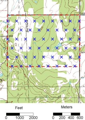
Samples were laid out using a 660 foot (200 m) Regular Grid pattern.
This is the simplest grid design because all the samples are 660 feet (200 m) apart vertically and horizontally.
The diagonal distance between samples is larger at 930 ft (280 m).
This type of layout works well on areas that have few obstacles and are geographically flat.
We design most sampling programs using a combination of topographic maps and aerial photos.
Sample programs overlaid on these basemaps show obstacles or difficult access, and the sample design can be adjusted before going to the field.
Good sample planning generally translates into more efficient sampling in the field.
Using the same area as above, a different sample layout is the Staggered Grid pattern.
Samples are 660 feet (200 m) apart horizontally. Every other sample line is offset one half sample spacing which decreases the
diagonal spacing between samples to 740 ft (225 m).
The red dashed line around the sample area is a digital boundary layered onto the map using program corner coordinates.
This boundary provides a guide line that is easy to see and shows program limits.
Notice the black dashed line labeled "Pipeline" running through the program.
Samples close to the pipeline would need to be moved for safe interstitial gas sampling.
All underground utilities need to be located and flagged before probing or drilling.
Staggered Grid
-
• Equal horiztonal distance
• Offset of 1/2 horizontal distance on
every other row
• Decreased diagonal spacing
Equidistant Grid
-
• Equal distance between samples
• 3 nearest samples form equlateral triangle
• 6 nearest neighbor samples form a hexagon
around a center sample
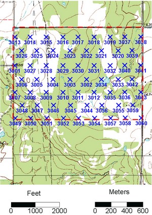
This example is a 660 foot (200 m) Equidistant Grid. Each sample is the same distance of 660 feet (200 m) away from each surrounding sample.
This pattern is sometimes called a "triangular grid" because 3 nearest neighboring samples form an equilateral triangle,
or a hexagonal grid because 6 nearest neighbors form a hexagon around the center sample.
Sample points were laid out digitally, and show Identification numbers at each sample location.
Unique sample numbers tie together map locations, GPS locations, and laboratory data.
Another example program was designed for high sample density in a selected area to meet a particular objective.
Samples are in rows of three and closely spaced at 200 feet (60 m).
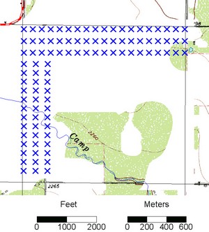
Custom Sample Grid
For information on shallow soil sample collection, click here to view.